Like Tribbles, Lego seem to have an uncanny ability for multiplying in my house at an almost exponential rate. First, you build models, then it’s Star Wars, then it’s your phone, your jewelry. Before things are said and done you’ve got nooks, bins and chests full of them. I’ve been addicted to Lego for longer than I can remember, so when the opportunity comes up to work on a new project of some sort the question that invariably arises is, “Can I use Lego?”

When I first looked into building my next computer I had no intentions other than taking the system and speeding it up. The once venerable overclocked Phenom quad-core system, with its dual Raptor HDs in a RAID 0 and other hardware was starting to show its age. I decided that this time around it was time to start a new platform. I had been making upgrades to my AM2 based AMD system for a couple of years and it seemed like the platform had served admirably but was reaching the end of the road.
Around the time I began my planning I beginning to be involved in Grid Computing. I liked being able to use one of my geek hobbies in a way to help try and benefit others. Grid Computing (http://en.wikipedia.org/wiki/Grid_computing) allows for using your home computer (through the addition of a small free downloadable program) to use its CPU and or GPU for the purpose of processing data in the form of research problems, equations, and more. Normally, it takes a supercomputer days, weeks, or months to works its way through some of this research. Grid Computing leverages the power of hundreds of thousands of computers whose users donate their processing time to make this happen.
Since I was going to be building a new computer anyway it seemed like the perfect time to maximize my build for Grid Computing (Crunching). My first plans were to focus on a multi-GPU setup that would be a dual purpose crunching/work machine. I encountered a problem in that my Grid Computing program of choice did not offer any GPU compatible projects, only CPU compatible. My main goal was Grid Computing with medical research and humanitarian projects in mind. For this reason I chose to go with IBMs World Community Grid as it offered a lot of these types of research. (Cancer, Aids, Muscular Dystrophy, etc.) http://www.worldcommunitygrid.org/
My plans changed when I realized I wouldn’t be able to make use of a GPU folding farm. The type of Grid Computing I wanted to do required CPU power in the form of multiple fast CPU cores. My first plan was to build a dual CPU Xeon based platform with a EVGA SR2 board. Some of the SR2 based systems I was finding were jaw-dropping; the performance was out of this world. But such performance comes with a high price tag. I had planned on using my normal budget of $1,500-2,000 and doubling it when I decided to build a Grid Computing computer. I decided that the money was a small donation in terms of trying to help a much larger cause.
My initial goals with my new system were as follows-
$2000 budget goal
100,000 Points Per Day (Points are used as a rough estimate of computational power)
Energy Efficient as possible
After pouring through and reading for hours in the forums I started to realize that the SR-2 monsters I had seen huge numbers from were also somewhat fickle beasts with RAM and some other settings. At that point I realized I wanted to go a different direction. I started looking more carefully at the computers I already had in my household and also looking at the electricity costs to run all these systems in addition to adding the new Folding computer. I already had a quad core workstation computer and a slightly lower end intel Core2 system running a touchscreen in my kitchen, and a server. Adding a fourth machine gave me pause.
I began thinking a little harder about the whole project. I wanted this to be efficient, at least relatively speaking. I turned my direction briefly towards building a multi-CPU setup based on a server board. This would have satisfied my requirements for multiple CPU cores. The downside of course was the cost. Server CPUs are expensive, as is the motherboard that supports them.
I was stymied for a couple of days on this whole project. I knew what I wanted, but couldn’t formalize a plan to pull it off. As I was working on other people’s computers and staring at the pile of pulled motherboards sitting on my bench I got to thinking, why do I need to have a bunch of separate cases and power supplies? Why couldn’t I build one system that housed multiple motherboards and CPUs? I could use desktop parts that were cheaper and consolidate all of my PCs into one.
Based on this I started to put together a parts list-
3x Motherboards
3X CPUs
3x CPU Coolers
2x GPU (Only 2 of the systems needed video, the third is remote operated)
3x Power Supplies??
3x Computer Cases??
Multiple Hard Drives and SSDs
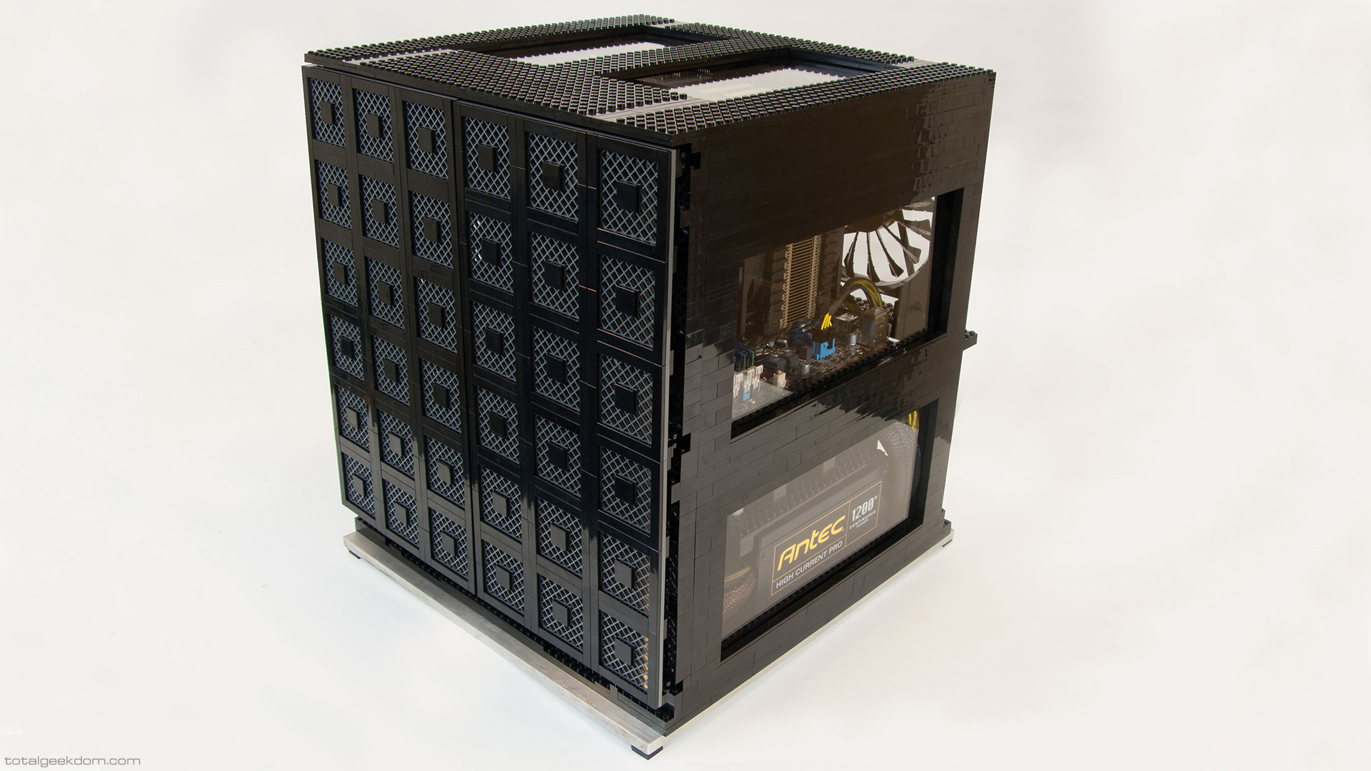
Now that I had a plan I started doing some research. I wanted to use the highest rated efficiency power supply available, but I did not want to buy multiple power supplies since that seemed inefficient with the power loss I would have per power supply. When I calculated out the power requirements of each sub-system it seemed like I was going to be right around 350 watts. This started me thinking, why can’t I just get one power supply with output around 1100-1200 watts and wire it for all three systems? This would give me the efficiency of buying the best Gold rated power supply along with saving some money. After a little more research I found what I was looking for; the Antec 1200 High Current. According to reputable online power supplies sites and reviewers this was the bad boy I wanted.
Cases presented my next challenge. I had an idea in my head what I wanted the case to look like, but after researching I couldn’t find something to fit my vision.
This takes me all the way back to the beginning. With every project I do I always invariably arrive at the same point, “Can I use Lego?” VOILA! YES! Lego! Lego and computers definitely sounded like a good combination. In reality the structure of a case built from Lego was going to require a fair bit of thought. I needed to get my case laid out correctly and able to support the weight of all the components without Legos buckling or falling apart.
Now that I had a solid plan I got underway with buying parts for the project-
3X Sandy Bridge 2600k CPUs
3x Thermaltake Frio Cpu Coolers
3X Asus P8P67 Micro atx motherboards
1x Antec 1200 HCP Power Supply
2x Corsair SSD (System 1/Workstation)
1x Mushkin SSD (System 2/Touchscreen)
1x WD HD (System 3/Folding Only)
3X DDR3 for each system
8x Aerocool 140mm Case Fans
1x Metric Crapload of Lego Bricks (Technically it was about 2,000pcs)
Through careful timing of Newegg sales, along with promotional codes and rebates I was able to get all the computer parts for right around $1,800. As far as Legos, I already had a lot of the black pieces I would need for this build, and I purchased the others I thought I would need in addition.
I eagerly awaited all of the goodies in the mail from Newegg. On the day the first batch of parts arrived I quickly tore into them and started tinkering.
My first step was bench testing all the parts. After that I started working on modifying the harness of the power supply to fit all 3 systems. After a little bit of work I finally had everything plugged in and ready to be test fired. I hit the button and all 3 systems lit up! I used my test stand to then test each system to ensure everything was running as it should be.

Power Supply & Motherboard Test

Multiple Systems with Single Power Supply

All Systems Running
Case Design
Once the testing was done I quickly moved my focus to building the case. I had a veritable mountain of Legos before me to work with. I slowly started to piece together the design that I had envisioned in my head. I had planned to incorporate some clear Lexan windows into the case. I purchased some Lexan and cut it down to what I thought was the appropriate size. The next step was mounting of the motherboards. I wanted to stick with a basic design philosophy; loading in a downward direction only. The outside walls of the Lego case actually support the load and weight of the components. Trying to hang anything of a significant weight from Legos will pull them apart. This is why the weight must always be pushing them together.

Lego Computer Case Level 1
In order to accomplish this I used a couple of thin pieces of aluminum bar, cut them to size, and drilled and tapped them to accept the motherboard screw pattern. These aluminum bars have the motherboards attached to them with regular PC case standoffs. The bars span the case and rest on each of the Lego walls and are encapsulated by Legos. This arrangement uses the weight of the components to apply a compressive force on the Lego walls and ensures that everything is stable. There are 4 of these aluminum bars. The first set at the middle section of the case supports the lowermost motherboard which hangs upside-down, and also the motherboard that sits directly on top of them right side up. The second set of bars sits across the top section of the case and supports the upper-most motherboard that is hanging upside-down. This arrangement of inverting the two motherboards allowed for me to pack a lot of components in a very small space.

Lego Computer Case Level 2

Motherboard Support Bars
Another thing I carefully considered was the overall airflow of the case and the layout of the components. I wanted a short, direct path of airflow from the front case fan directly into the CPU fan/cooler. Behind that, another open section leading to the exhaust case fan. Each CPU/cooler has its own intake and exhaust fan directly in front and behind. The power supply also has this fan arrangement. The space between the motherboards was designed to allow for airflow over both the top and bottom surfaces of the motherboard to ensure maximum air cooling of the PCB and components attached to it.
Another thing I took into account was air pressure. Cases that have a lot of large air spaces, and voids tend to have low pressure over the components they are supposed to be cooling. Air takes the path of least resistance, which means given the option of flowing through a heatsink or around it, air will flow around it. I attempted to avoid creating paths where air could flow through dead space without cooling anything. This is part of the reason that the components are spaced so close together. I also made sure to buy case fans that had a higher pressure rating to make sure I had adequate pressure to correspond with the airflow.
I attempted to do my best to cover and hide wires. This was both from a standpoint of appearance and also for avoiding possible interference to airflow. Many sections have wire hidden or concealed under Lego panels to provide a cleaner look.

Power Supply Wire Concealing
Testing
After getting the majority of the case structure done I moved onto wiring. To say I had ten pounds of wires in a two pound basket is an understatement. It was tedious work ensuring all the wires were out of the way of the airflow paths and components, especially with having the wiring of all 3 systems crammed in such a small area.
After getting everything setup, I worked on installing Windows 7 on the first system. The install went very quickly and before I knew it I was in Windows configuring the SSD RAID 0 setup. I then moved onto the other 2 systems and did the Windows installs and configurations on them also.
Once I had all 3 systems up and running I went to work on overclocking. The new UEFI BIOS was a bit unfamiliar at first, but after some tinkering I got the hang of it. I played around a little with the settings and soon enough I was staring back at a 4.7Ghz number for each of the CPUs. I setup each system running an instance of Prime95 and let the machine go overnight to test my stability. When I returned the next morning I was happily greeted by all 3 machines still running without errors and with temps right at the 60-65 degree mark.
Seeing that the overclocked systems had all performed without error, I pulled up the World Community Grid/BOINC program on each system and started crunching. After a couple of days it looked like my average points per day was about 43,000 to 47,000 points per system. With all 3 systems crunching as a team this gives me a per day average of around 135,000 points. Given that my old system used to average about 10,000 or so points a day I would say I’m very happy with these numbers. I’ve managed to increase my folding/crunching performance by a factor of about 13 while only increasing my power requirements by about double.
Since my UPS has an LCD readout that displays wattage consumption I used it to compare the differences in power between my old system and the new folding farm. Not exactly super-duper accurate, but close enough for comparison sake.
AMD Phenom Quad Core System- (4 CPU Cores, 4 Threads)
Full Load- 350 Watts
Folding Farm Sub-System- (4 CPU Cores, 8 Threads)
Full Load- 270 Watts (Including all case and CPU cooler fans)
Entire Folding Farm- (12 CPU Cores, 24 Threads)
Full Load- 600 Watts
Instead of having 3 separate computers taking up my desk space I now have one system that functions as three. I sold off the two other computers I had to recoup some money from this build as well. In the end the most important thing to me though is that I feel like I’m doing more to help contribute to a good cause in humanitarian and medical research. I know it’s just one system, but every little bit counts in finding cures and solutions.

Lego Computer Case Design Upper

Lego Computer Case 2nd Level

Mounted Upper & Lower Motherboards

Lego Computer Case Upper Design
Numbers
Folding Farm vs. Old Workstation PC
Folding Farm-
Crunching Points Per Day Average- 135,000
Power Consumption Full Load- 600 Watts (UPS Measurement)
Old WorkStation PC-
Crunching Points Per Day Average- 10,000
Power Consumption Full Load- 350 Watts (UPS Measurement)

Lego SSD Mounts

Upper Systems Installed

Top Case Windows

Finished Upper Lego Case

Lego Computer Case Front Layout

Front Fan Case Mounts

Front Case Fans

Lego Computer Case Doors Open

Lego Computer Case Doors Closed
Notes
Operating System
I choose to use Windows 7 as the operating system for all 3 systems primarily because I already had copies I had bought and installed on the other computers. There was no added cost for me to keep using it. Additionally, I have a Windows Home Server that plays very nicely with all the other Windows 7 machines and wanted to keep it that way. The remote desktop function native in Windows 7 also makes it brain-dead easy to remote in from any other computer to keep up with the folding progress.
If you were starting off from scratch and the operating system cost was a factor you could very easily repeat this setup using Linux instead. This would save the cost of the operating system and give you a lot of the same functionality.
Lessons Learned
The entire build process had me looking for solutions to problems that arose during construction. As I look further in detail at certain areas I think there are changes I would make with future builds.
Add lower, middle and upper layer between sections about 1″ thick that would have openings for all the wiring to go into and be concealed. This would allow for an almost complete elimination of wiring to work around and organize.
Get more rounded Legos and other shaped pieces that would allow to create more aerodynamic surfaces for airflow in certain parts of the case.
Heatpipe Coolers
One area of concern I had initially was the orientation of the CPU coolers. The reason being that the coolers I chose to use are a Heatpipe style cooler. This type of cooler uses tubes filled with a liquid that go through a phase change from a liquid to a vapor to release heat. The issue I thought I might have is that if you invert the cooler (by installing the motherboard upside down) that you would not allow the cooler to function properly because the liquid was moving in the heatpipes as a function of gravity.
I made some calls to Thermaltake which put my fears to rest. The cooler uses a capillary action inside the heatpipe in this model that allows the liquid to move back to the base of the cooler no matter what direction it’s mounted. Keep in mind that there are motherboards which use heatpipe coolers on the PCB directly and these may not have this same internal capillary function.
Z68 versus P67 Chipsets
When I started this build I had wanted nothing more than onboard graphics, which are native and built into the Sandy Bridge CPU architecture. However because of the way that Intel was offering chipsets at the time you only had two choices, you either got a H67 with onboard graphics capabilities and no overclocking ability, or you got a P67 with no onboard graphics but with overclocking ability. Because of this I was forced to go with a P67.
Fast forward to the present and Intel now offers the Z68 chipset which offers both onboard graphics and overclocking. This is definitely something I would have preferred since there would’ve been fewer components to worry about and, more importantly, less wattage required.
Power Switch
Testing out the multi-system wiring and the power supply I found that if you just used one power switch it would turn on all the systems and shut them all off at once. However, it would not turn on every portion of each system, just the main power and fans. Missing was the triggering to enable graphics and a few other things. I had to wire the switch to activate all three boards at once in order to get correct operation. You could accomplish the same thing by having three separate switches and turning them all on, but I went ahead and just wired it with one switch. Granted, this system runs 24/7 so it will be rare that I will ever be turning it off and on.
Airflow
I’ve been experimenting with adding Lego pieces in various parts of the case to alter airflow paths and try and focus the air more on the things I want to cool and less on the dead space of the case. After trying a couple of different variations in air dams and directional vanes, I’ve noticed the temps move around quite a bit. So far I’ve managed an additional 2-3 degree drop by adjusting and optimizing airflow. I plan to continue using this system as a test-bed for further airflow and case development.
Future Upgrades
When I built the case I tried to keep the design fairly symmetrical in the upper level that houses the two motherboards. My goal was to be able to add another level at some point down the road and add an additional two folding only sub-systems. For this reason I intentionally chose a power supply that was larger than I needed. The power supply needs to operate somewhere between 50-90% of its peak in order to run at maximum effciency. I should have enough power in reserve to add more sub-systems down the road. I also drilled and tapped the upper most set of aluminum bars with the micro-atx motherboard layout on the other unused upper side. Hopefully when the time comes this will simplify adding another level on top.

Lego Computer Technician